
The idea to build this experimentation prototype came to me after a heated discussion with a colleague at UCLA regarding whether or not light sensor information can be used to reliably localize light sources in 3D. So what does it do?
Briefly speaking, the experimentation prototype here:
- Collects data from light sensors
- Computes the position and intensity of a light in 3D space
- Graphically displays the results in real time
- Computes the position of a light compass given the position of a light source(s).
- Can determine faulty and/or obstructed sensors
- Provides a means to check the accuracy of the computed results in real-time.
The set up is fairly straight forward. I wired 8 photovoltaic sensors directly to a simple ADC module which I read through bit-banging the parallel port on a standard PC. The hardware is able to reliably achieve more than 10Hz sampling per sensor which was more than enough for my needs.
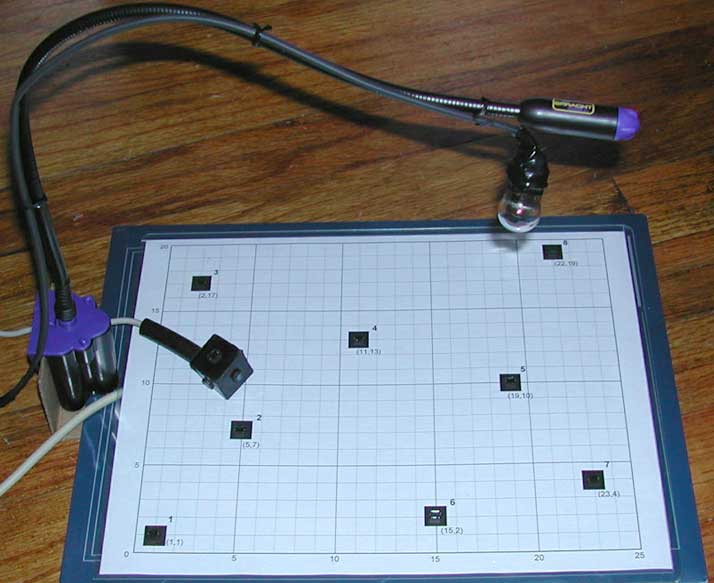
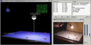
Each sample consists of one byte of voltage read from each sensor. The sensors produce roughly in the range of 100mV to 400mV in a typical indoor setting. As you can see in the picture below, I have arranged the 8 photovoltaic sensors in a "random" arrangement on a 2D plane (standard 8.5"x11" sheet of paper). The location of each sensor and the surface normal (in this case all perpendicular to the plane of the paper) are input to the light modeling program that I wrote.
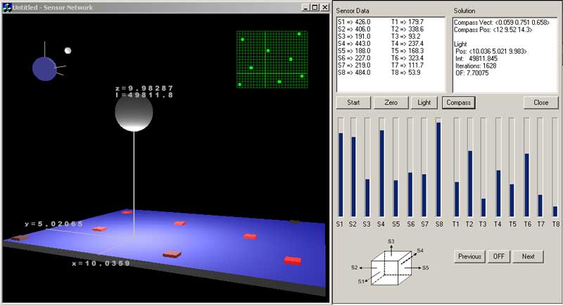
Below is a screen-shot of what I display on the PC screen through the C++ application (MFC/OpenGL). The software communicates with the data collection subsystem using standard sockets (UDP). On the right, the raw data received from all the sensors is displayed both in text and bar-graph forms. I then programmed a simple conjugate-gradient based non-linear solver to take the readings from the sensors, combined with their positions and surface normal information to compute the position and intensity of a point light source <x,y,z,I>. The graphical result is then displayed in 3D on the left with the size of the sphere corresponding to the light source indicating the computed intensity of the light.
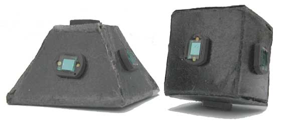
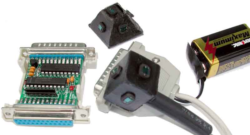
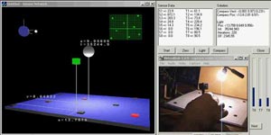
The pictures above show the light compass prototypes that we designed while pondering the details of this problem. The idea here is to mount multiple sensors on the surfaces of a rigid body with different surface normals and use the additional information obtained by these sensors to compute more things about the object and the environment. For example, as can be seen in the second video link below, the data collected by such a light compass can be used to determine the position of the object in 3D (assuming the orientation and the position of light sources is known). On the right, you can also see the ADC hardware used here.
For further details on the design of the light compass, please refer to:
- J. L. Wong, S. Megerian, M. Potkonjak. "Design Techniques for Sensor Appliances: Foundations and Light Compass Case Study." 40th IEEE/ACM Design Automation Conference (DAC 2003), pp. 66-71, June 2003.
Video Demos | |
|
 |
|
 |
Note: You may have to right-click and save the video files first.